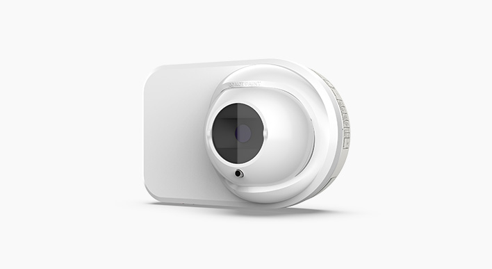
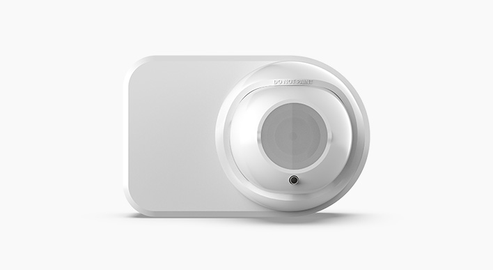
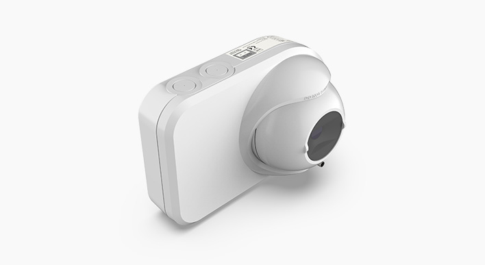
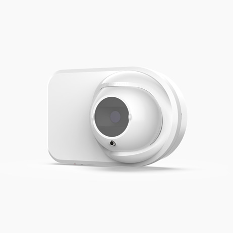
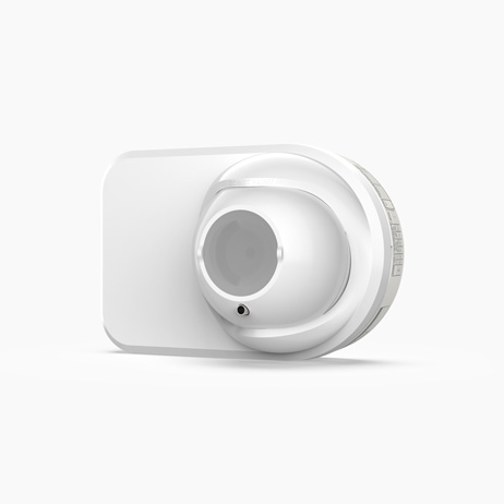
Key Features
- Maximum detection range of 150m
- Status LEDs for Fire, Trouble and Power
- High false alarm immunity
- Dust and intrusive solid object rejection
- Easy alignment with large adjustment and viewing angles
Overview
Open-area Smoke Imaging Detection (OSID) is a new innovation in projected beam smoke detection technology. By using advanced dual wavelength projected beams and optical imaging technology for early warning smoke detection, OSID provides a low-cost, reliable and easy-to-install solution that overcomes typical beam detection issues such as false alarm incidents and alignment difficulties.
Unique Detection Technology
The OSID system measures the level of smoke entering beams of light projected over an area of protection. A single OSID Imager can detect up to seven Emitters to provide a wide coverage area. Two innovations in smoke detection technology have been developed for the revolutionary OSID smoke detector:
Dual Wavelength Particle Detection
The beam projected from each Emitter contains a unique sequence of ultraviolet (UV) and infrared (IR) pulses that are synchronised with the Imager and enable the rejection of any unwanted light sources.
By using two wavelengths of light to detect particles, the system is able to distinguish between particle sizes. The shorter UV wavelength interacts strongly with both small and large particles while the longer IR wavelength is affected only by larger particles. Dual wavelength path loss measurements enable the detector to provide repeatable smoke obscuration measurements, while rejecting the presence of dust particles or solid intruding objects.
Optical Imaging with a CMOS Imaging Chip
An optical imaging array in the OSID Imager provides the detector with a wide viewing angle to locate and track multiple Emitters. Consequently, the system can tolerate a much less precise installation and can compensate for the drift caused by natural shifts in building structures.
Optical filtering, high-speed image acquisition and intelligent software algorithms also enable the OSID system to provide new levels of stability and sensitivity with greater immunity to high level lighting variability.
Operation
Status information (Fire Alarm, Trouble and Power) is communicated through the Imager via Status LEDs, dedicated Trouble and Alarm relays, and the Remote Indicator interface. Specific Trouble (Fault) conditions are identified through coded flashes of the Trouble LED.
An internal heating option is also provided on the Imager to prevent condensation on the optical surface, and a reset input enables an external signal to reset the device.
Simple Installation and Maintenance
The OSID system consists of up to seven Emitters, for the 90° Imager unit, located along the perimeter of the protected area, and an Imager mounted opposite. Each component can be mounted directly to the surface or can be secured with the supplied mounting brackets.
On the Imager, a termination card provides all field wiring terminals, and DIP switches enable the user to configure the detector for particular applications.
Alignment of the Emitter is simply achieved using a laser alignment tool to rotate the optical spheres until the laser beam projected from the alignment tool is close to the Imager.
The Imager is aligned in a similar way so that its Field of View (FOV) encompasses all Emitters. A Trouble or Fault will be indicated if an Emitter is missing or outside the Imager field of view.
The OSID system is highly tolerant to dust and dirt and requires little maintenance in practice. Preventative maintenance is limited to occasionally cleaning the optical faces of the detector components.
Additional Features
- No need for precise alignment
- Tolerant of alignment drift
- Automatic commisioning in under ten minutes
- Simple DIP switch configuration
- Dual wavelength LED-based smoke detection
- Simple and easy maintenance requirements
- Conventional alarm interface for straightforward fire system integration
- Three selectable alarm thresholds
Approvals


The OSID is fully approved by VdS for safe use and installation in any European Union country and bears the CE mark to show that it complies with all the applicable Directives including the CPR, EMC and the Low Voltage Directive (LVD).
- BS EN 54-12:2015
Fire detection and fire alarm systems. Smoke detectors. Line detectors using an optical beam.
Configuration Options
OSID systems may be configured to suit a range of detection spaces by selecting the number of Emitters and type of Imager. Each type of Imager differs by the lens used in the unit, which determines the field of view and range of the system.
| Field of View | OSI-10: 7° Horizontal, 4° Vertical OSI-90: 80° Horizontal, 48° Vertical |
| Detection Range | OSI-10 with OSE-SP-01/OSE-SPW: 30m (98ft) to 200m (656ft) OSI-90 with OSE-SP-01/OSE-SPW: 6m (20ft) to 34m (111ft) Maximum Distances measured for the Center Field of View of the Imager. For more details on distances for the Imager, see the OSID Product Guide. OSI-90 with OSE-HP-01/OSE-HPW: 12m (39ft) to 68m/50m* (223ft/164ft) Distance with OSE-HP-01 |
| Maximum Number of Emitters | OSI-10: 1 OSI-90: 7 |
Tech Specs
| Alarm Thresholds (Configurable) | Low – Highest sensitivity / earliest alarm: 20% (0.97 dB) Medium – Medium sensitivity: 35% (1.87 dB) High – Lowest sensitivity / maximum immunity to nuisance smoke conditions: 50% (3.01 dB) Industrial mode – unapproved sensitivity at 65% (4.56 dB) |
| Alarm Latching (Configurable) | Latching / non-latching configured via DIP switch |
| Status LEDs (Imager) | Red: Fire Alarm; Bi-color Yellow/Green: Trouble or Normal |
| IP Rating | IP44 for Electronics; IP66 for Optics Enclosure |
| DIP Switch Configuration (Termination Card) | Configuration for alarm thresholds, number of Emitters and alarm latching/non latching |
| Imager Supply Voltage | 20-30Vdc (24Vdc nominal) |
| Imager Current Consumption | Typical at 24 VDC: 8mA (one Emitter), 10mA (seven Emitters) |
| Emitter Current Consumption | Externally powered Emitter (at 24Vdc): 350μA Standard Power, 800μA High Power Battery-powered Emitter: Built-in 5 Year Replacement Alkaline Battery, 3 Year Replacement with OSE-HP-01 Battery life time is only valid for use at room temperature. |
| Cable Gauge | 0.2 – 4mm2 (26-12AWG) |
| Trouble/Fault Relay | 2A @ 30Vdc, NO-C-NC Dry Relay Contacts |
| Fire Alarm Relay | 2A @ 30Vdc, NO-C-NC Dry Relay Contacts |
| Heater Input Power | 24Vdc, 16mA (400mW) |
| Operating Temperature | -10ºC to 55ºC (14ºF to 131ºF) |
| Humidity | 10 to 95% RH Non-condensing |
| Dimensions (W x H x D) | 208mm x 136mm x 96mm (8.2in x 5.4in x 3.8in) |
| Weight | Imager: 610g Emitter (battery powered): 1.2kg Emitter (wired): 535g |
| Adjustment Angle | Horizontal: ±60º; Vertical: ±15º |
| Maximum Misalignment Angle | ±2º |
Downloads
Buy

Eurofyre is an authorised distributor of Honeywell and has been a major technical wholesaler of Xtralis products since 2007. We offer expert advice and supply all aspects of VESDA, FAAST and ICAM aspirating smoke detection systems including pipework calculations, demonstration/training and excellent after-sale support.
Contact us to receive competitive trade discounts or apply online for a credit account.
